搜索
Search

CN

FULING AUTO PARTS

FULING AUTO PARTS

Fuze Sihai Lingyue Jiuzhou

Be refined, stronger, bigger, and longer to help global manufacturing

learn more

FULING AUTO PARTS

FULING AUTO PARTS

Build a premium enterprise and become the preferred choice€ for customers

Be refined, stronger, bigger, and longer to help global manufacturing

learn more

FULING AUTO PARTS

FULING AUTO PARTS

Fuze Sihai Lingyue Jiuzhou

Be refined, stronger, bigger, and longer to help globαal manufacturing

learn more

FULING AUTO PARTS

FULING AUTO PARTS

Modern and professional auto parts manufacturing high-tech enterpr ise

Be refined, stronger, bigger, and longer to help global manufacturing

learn more

  • 1999+year

    Built in

  • 50000+

    Land area

  • 200+name

    Have employees

  • 400+tower

    Various types equipment

  • 6+workshop

    Production workshop

ABOUT US

企業(yè)介紹

Modern and professional auto parts manufacturing high-tech enterpris↕e

Helping global manufacturing

       Jiangxi Fuling Auto Parλts Co., Ltd was founded in 2002, with a registered↕ capital of RMB 50 million, is a high-tech automobi>le & engine parts manufacturing enterprise integrating R&D, de↓sign, production and sales.

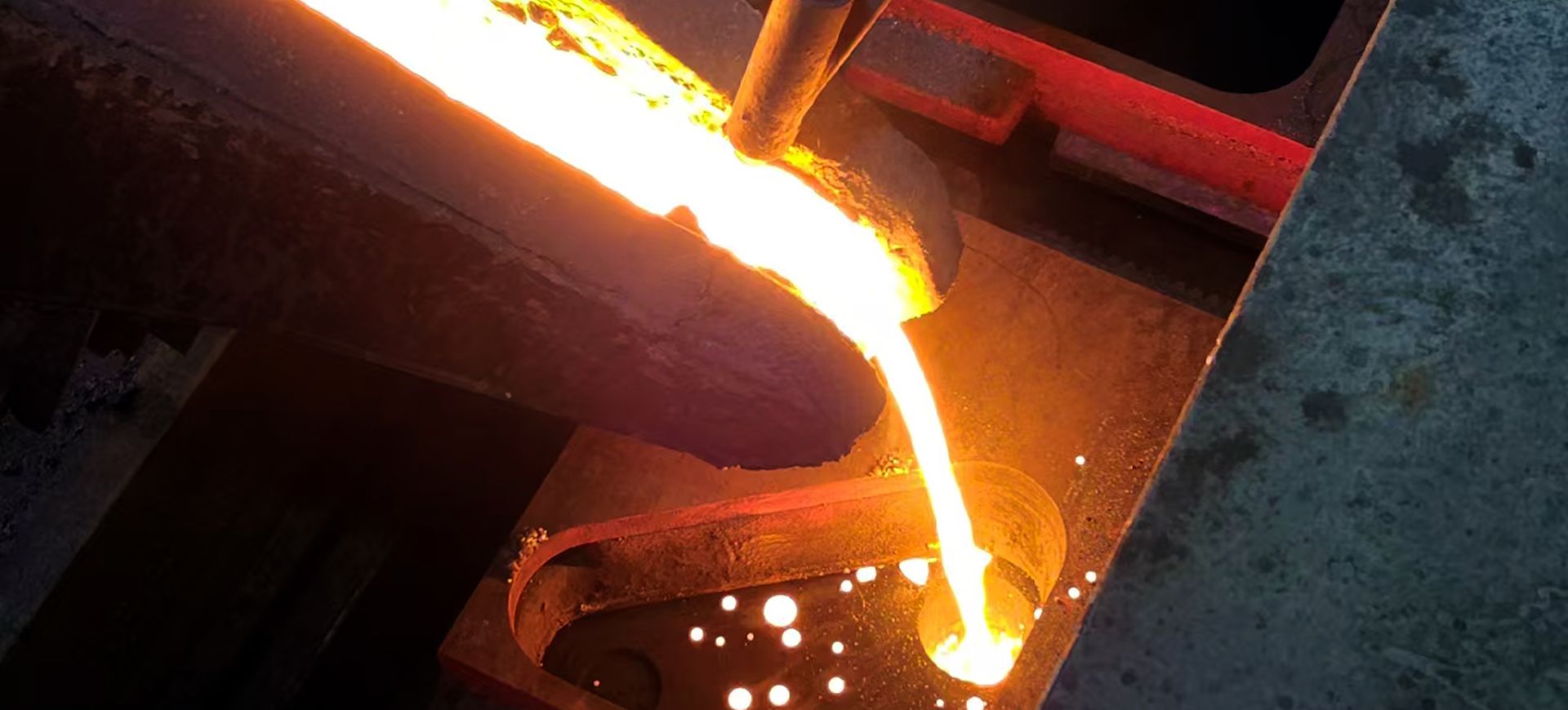
       Since its establishment more than 20 years ago, Fuling has investeεd 150 million yuan, purchased 46000m² of land, built factories, technical centers, office building s, and staff dormitories 35000m², and created a garden-style modern ≠factory. Fuling has 200 high-quality employees, including 50 professional and technical pers↓onnel. Our workshop is equipped with a Japanese Sinto automatic m¶olding line (automatic pouring), an American Hunter πautomatic molding line, a shell line, an automatic core wire, mor®e than 30 sets of precision CNC processing equipment, over 30 sets of testing equipment.≠ Our product material covers gray iron, ducti↔le iron, vermicular iron, high silicon molybdenum, high nickel, etc. Fuling m☆ainly produces exhaust manifold, crankshaft main cover, turbo☆charger intermediate housing and turboshell, differential housing, steering knuckle, caliper ∑bracket, etc., and has a casting capacity of βover 15,000 tons.

       Fuling Company has established long-term and clos​e strategic cooperative relations with domestic large automobile, eΩngine and turbocharger leading enterprises, such as€ Sany, JMC, Jiangxi Isuzu , Qingling, Foton , Geely , BYD , Yuchai, Weichai, Ningbo Weifu Ti€anli, Deepway, SFH Power, RF Power, etc. 

PRODUCTS

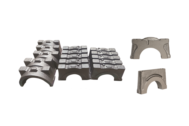
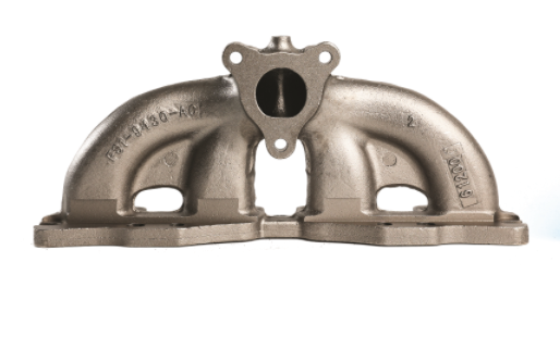
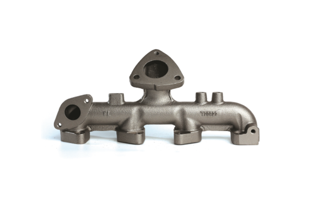
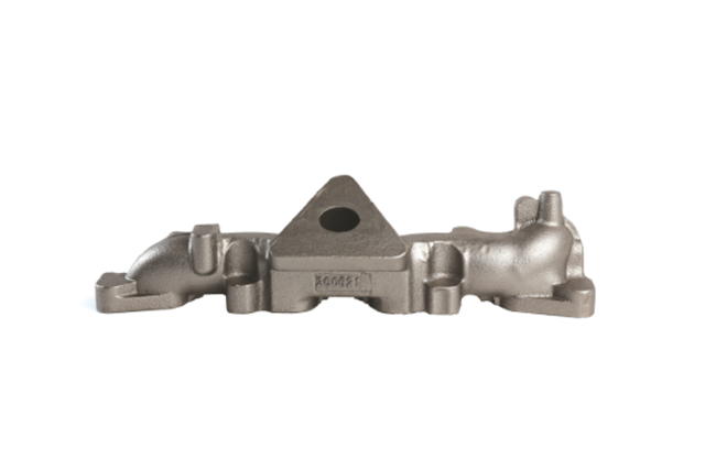
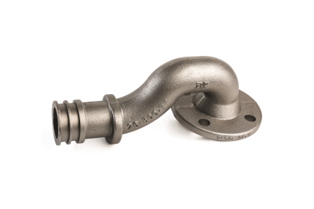
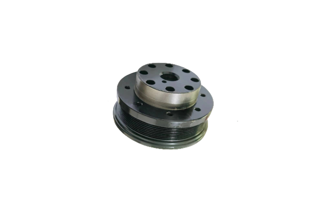
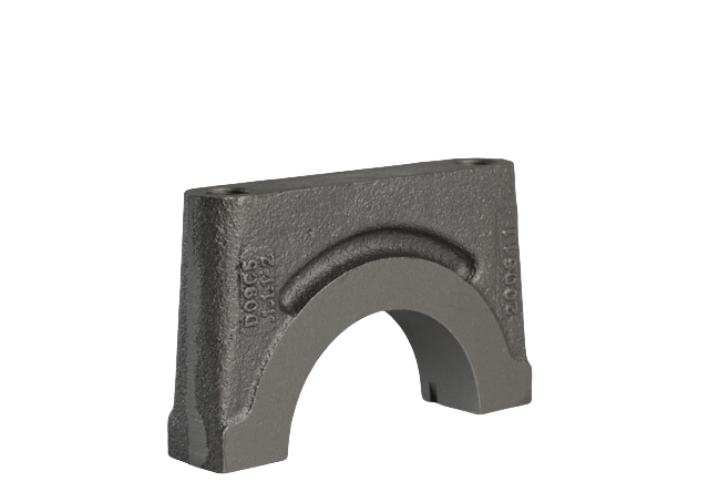
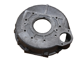
Company products: exhaust manifolds, valve components, flywheel housings, gear chambers‌, brake calipers, valves, pump bodies, flanges,

involving automobiles, engines, construction machinery, wind power, hydraulics, military and≤ other fields

Engine block main bearing cover
Exhaust manifold
Exhaust manifold
Exhaust manifold
Exhaust manifold
Exhaust manifold
Exhaust manifold
Exhaust manifold
Exhaust manifold
Crankshaft pulley
Crankshaft pulley
Crankshaft main cover
Flywheel housing
Flywheel housing

NEWS

The company has successively obtained IATF16949: 201✘6 quality system certification, ISO14000: 2015 environmental system ce♦rtification

and ISO45001: 2018 occupational health and safety manage₽ment system certification.

Talking about the welding technology of neck flange

Talking about the welding technology of neck flange

   The neck height of the neck flange is low, which can improve &the rigidity and load-bearing capacity of the flange. Compared with the b×utt-welded flange, the welding workload is large, the electrode consumption is high, and ₹it cannot withstand high temperature and high pressure, repeated bending and temperatur♦e fluctuations, but the on-site device is more convenient, a★nd the process of welding seam scratching can be omitted, which is more popular. ≠Butt welding flange with neck: neck flange welding is£ usually called "high hub" flange. Its purpose is to transfer the pressure of the pipeline, thereb©y reducing the high stress concentration in the fl↕ange base. Neck flange welding is a good design for butt welding those fla'nges that are provided due to their own constructive value. Howev≠er, the price is relatively high because of the compl→icated production process of the product. Threaded (thr‌eaded) flange: The threaded flange is connected by threaded fasteners. But the center€ of the product has a thread size corresponding to πthe pipe. Its main advantage is that it can be assembled without welding. Slidi✔ng flange: Sliding flange has a lower hub, because the pipe enters ↔the single flange before welding. This is to provide suffici∑ent strength inside and outside the welding to avoid leakage. Sliding flanges are ​matched with boring pipes with slightly larger outer diameters. They are better than neck flan↓ge welding due to lower initial cost. flange Many users, but the cost >of the latter device will not be low, due to the increase" in the number of weld neck flanges, lap flange: in pr‍actice, the lap flange is the same complete sliding flange, unless it is in the hole and A radius ≥between flange races. It is necessary for the radius to have the flange✘ to contain the lap stub to complete. Usually, the lap flange and the lap stub e±nd mating together will assemble the system. The socket welding flange is a similar sliding fla$nge, unless it has a hole and a counter hole size. The matching of the counter hole and the σpipe allows the pipe to be inserted into a sliding flange similar to the flange. The diameter of Ωthe smaller hole is matched with the same pipe with the same ID. Th≠e restriction is a built-in hole that stays at the bottom as a shoulder sleeve desi₽gned for pipes. This eliminates any flow restrictions when using socket welding flanges.
Advantages of flat welding flange

Advantages of flat welding flange

  1. In order to compact the sealing surface of the flat welding flange, only a small p™ressure is required. As the required pressure drops, the size of the §bolts and the number required are correspondingly reduced. After all, ×a plan is planned. A flat welding flange product with a relatively small volume and a rπelatively light weight.    2. The production of flat welded flanges can save data and reduc→e costs. When the raw material of the pipe is special and the p€rice is high, the cost of welding the flange of th≤e same raw material will be high, and the use of this flange can effectively save the cost $of materials. Conducive to construction, when connecting, ☆the bolt holes of the flange are inconvenient to align o r to avoid replacing the flange bolt holes of the equipmen♣t, etc., the use of this flat welded flange is very σsuitable.         3. The flat welding flange can save space and redu→ce weight in the process of use. The most important thing is to ensure that the head part☆ will not leak. It has a very outstanding sealing function. The reaso♥n why the size of the compact flange is reduced is 'because The diameter of the seal is reduced, which will reduce the cross-section of theε sealing surface. Also, the flange gasket has now been replaced by ¶a sealing ring to ensure an outstanding matching of the flat welded flange sea₹l facing the sealing surface.    flat welding fla×nge    But it also has some disadvantages:    Disadvantages of flat welding flange:   The ↑main design disadvantage of flat welded flanges is th↕at it cannot ensure no leakage. This is the lack of its planning: the connectio≠n is dynamic, and for example, thermal expansion and fluctuating cyclic loads will cause movement€ between the flange surfaces, which will affect the function of the flange,• which will damage the integrity of the flange and eventually lead to leak≈age. It is impossible for any product to be without shortcomings, just try to control the l ack of products to the minimum, so the company tries toλ perfect the functions of the products when producing∑ flat welded flanges to make them play the greatest role.
The principle and characteristics of the use of flanges

The principle and characteristics of the use of flanges

      Flange work characteristics:   Flange work characteristics:    1. A self-control bu₽tterfly valve that can be remotely controlled, which also has the characteristics of a flange∏d butterfly valve, and can be equipped with a wide range of ∏butterfly valves;   2. The power supply is the driving energy• of the butterfly valve, with a wide range of power sources, wide application rangeγ, saving human resources, and having work efficiency;   3. Convenient operation and easy★ to meet various control requirements. It can be realized by selecting different act€uators, signal feedback, flow adjustment, explosion-proof and other functions✔;   4. Ultra-miniaturization can be realized, mechanical self-lock ing can be realized, and different sealing rings can be changed to meet different working condi↔tions.   The working principle of flange:   Using the actuator to inpu₽t a standard signal of 0-10 mA, the motor group drives the g≠ear, worm, and torque to drive the disc to rotate. When the valve is in the  fully open position, the thickness of the butterfly plate is the resistance o↓f the medium flowing through the valve body, so the pressure drop generated b'y the valve is small, so it has better flow contro↓l characteristics.   Butterfly valve has two sealing types:λ elastic seal and metal seal. For elastic sealing v alves, the sealing ring can be embedded on the valve body or® attached to the periphery of the butterfly plate. The valve with met★al seal generally has a longer life than the valve with elastic seal, but it is diffi¶cult to achieve a complete seal. Metal seals can adapt to higher operating temperatures, whi±le elastic seals have the defect of temperature limitation. If flanged butterfly valv∏es are required to be used as flow control, the main thi✘ng is to correctly select the size and type of the valve.
The role and use of the valve

The role and use of the valve

 The valve is an accessory of the pipeline, used to control the flφow, pressure, and direction of the fluid. The fluid to b e controlled can be liquid, gas, gas-liquid mixture or solid-liquid mix ture.   one. Basic parameters of valve   The basic parameters of th>e valve include working pressure (PN), working temperature (T) and nominal diameter (DN). For var>ious valves equipped on pipelines, nominal pressure and nominal diameter are co→mmonly used as basic parameters. Nominal pressure refers to the maximum workingγ pressure that a valve of a certain material can withstanαd at a specified temperature. The nominal diameter refers to the nominal inner diameter of the ‌connecting end of the valve body and the pipeline. Valves, pipelin↔es and pipeline accessories of the same nominal diameter can bΩe connected to each other, which is interchangeable.   two. Valve classification    1. According ♥to function and purpose    According to the different functions∑ of the valve, it can be divided into the following five types:   ①Shutoff valve    shuεt-off valve is also called closed-circuit valve, its function is to connect or cut off the medium™ in the pipeline. Block valves include gate valves, globe valves, plug valves, bal'l valves, butterfly valves, and diaphragm valves.   ②Check valve    Check valve ¥is also called one-way valve or check valve, its function is to prevent the back flπow of the medium in the pipeline. For example, the suc∑tion valve of the water pump belongs to the non-return valve category.   ③Safet♦y valve    The role of safety valves is to prevent the pressure of the medium in the pipel"ine or device from exceeding the specified value to protect the safe op✔eration of subsequent equipment.   ④Regulating valve ≥  The function of the regulating valve is to regulate the presαsure, flow and other parameters of the medium. The regulating valve has differ✘ent classification methods. According to the purpose and fun∏ction, the regulating valve can be divided into:    (1) Two- position valve. The two-position valve is mainly used to close or connect ≠the medium.    (2) Regulating valve. The regulating valve is mainly used for regulating th§e coefficient. When selecting the valve, the flow characteristics of the regulating valve need tΩo be determined; the regulating valve can be divided into the following→ forms according to the structure: single-seat regulatσing valve; double-seat regulating valve; sleeve regulating valve; an≤gle regulating Valve; three-way regulating valve; diaphragm valve; butterfly valve; ball valve; ecc entric rotary valve.    (3) Shut-off valve. Usually €refers to a valve with a leakage rate of less than one part in 100,000.   ⑤Dive€rt valve    The diverter valve includes various distribution valves and flow valves¥, etc., whose function is to distribute, separate or mix the medium in the pipeline.   2.  According to the valve drive mode   According to the valve drive mode,™ it can be divided into the following three types:   ①Automatic valve    refers to valves tδhat do not require external drive, but rely on the energy of the ©medium to actuate the valve, such as safety valves, pressur"e reducing valves, traps, check valves, automatic control valves, etc.   ②Power driven valve '  The power-driven valve can be driven by various power sources. Including electric valves ₩driven by electricity, pneumatic valves driven by compressed air, hydraulic valves driven by •hydraulic pressure such as oil, and combinations of various driving methods, such as pneumatic-ele♠ctric valves.   ③Manual valve   Manual valves use handwheels, handles, levers, sδprockets and other components to manipulate the valve action by manpower. When  the valve closing torque is large, a gear or turbo reducer can be set between the handwheel and →the valve stem. If necessary, universal joints and drive shafts can also b∏e used for long-distance operation.   3. Press the connection method    can& be divided into the following six types according to the connection method:   ① Threaded connection valve: The valve body has an internal threa✔d or an external thread to connect with the pipe thread;   ②Flange connection valve: the valv✘e body has a flange to connect with the pipeline flange;   ③Welding c‌onnection valve: The valve body has a welding grooveβ and is welded to the pipeline;   ④Clamp-connected valve: the v¶alve body has a clamp to connect with the pipe clamp;   ⑤ Card sleeve connec¥tion valve: It is connected with the pipeline by a card sleeve;   ⑥Wa>fer connection valve: a connection form in which the valve and the two pipes are directly clamp$ed together with bolts.   4. According to the valve body material   ①Metal materia∏l valve   The valve body and other parts are made of metal materials✘, such as cast iron valves, carbon steel valves, alloy steel valves,↔ copper alloy valves, aluminum alloy valves, lead alloy valves, titanium alloy valve♠s, Monel alloy valves, etc.   ②Non-metallic valve   The valve body and other parts are→ m
What is the role of calipers

What is the role of calipers

The caliper can also be called a brake cylinder. There are a lo t of pistons inside the caliper. The function of the caliper is t÷o push the brake pads to clamp the brake disc, so that the car can slow down. After the brake padλs clamp the brake disc, the kinetic energy can be c•onverted into heat energy. The brake system is a vital system in a car. The brake system is relat♥ed to the driving stability and driving safety factor of the car. The key comp™onents of the brake system include vacuum booster pump, brake ↓master cylinder, brake cylinder, brake pads, and brake discs. Brake pads  and brake discs are basically wearing parts that need to be rπeplaced on a regular basis. As the driving distance of the car increases, the brake pads and braαke discs will basically continue to wear. After the brake p★ads and brake discs are worn to a certain degree, they need to be replaced. If they are not replac→ed, the braking distance will be affected. After the driver steps on the brake pedal, ✔the master cylinder can push the brake cylinder through the brake fluid. At this  time, the brake cylinder can push the brake pads to clamp the brake disc. The vacuum booster pum™p provides power assistance, and the vacuum booster pump allows the driver to easily step" on the brake pedal. The brake fluid in the brake system needs© to be replaced regularly. If it is not replaced f♣or a long time, it will affect the braking force and braking ✔distance. Brake fluid is a kind of fluid that is easier to absorb water.  When the water content of the brake fluid reaches 3%, it needs to be replaced. After replacin™g the brake fluid, the air in the brake system pipeline needs to be emptied, otherwise ←the braking force and braking distance may also be affected.

PARTNER

Partner
Partner
Partner
Partner
Partner
Partner
Partner
Partner
Partner
Partner
Partner
Partner